Let’s first understand an engine with 1 upstream oxygen sensor, 1 catalytic converter, and 1 downstream oxygen sensor. This setup is common in many vehicles, with one sensor located before and one after the catalytic converter.
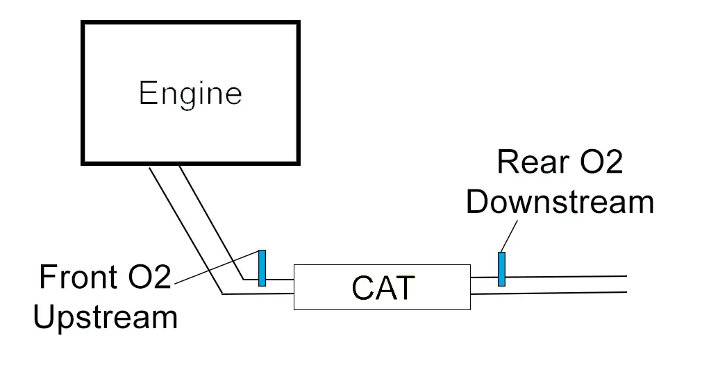
Function of Each Sensor:
- Upstream O2 Sensor: Measures the air-fuel ratio before the exhaust gases reach the catalytic converter. Helps the ECU adjust the air-fuel mixture for optimal combustion.
- Downstream O2 Sensor: Monitors the performance of the catalytic converter by checking the oxygen levels after the exhaust gases have passed through it.
What is a Catalytic Converter?
- Function: The catalytic converter reduces harmful emissions (like CO, HC, and NOx) by converting them into less harmful substances like CO₂, water vapor, and nitrogen.
- Interaction with O2 Sensors: The upstream sensor adjusts the engine’s fuel mixture, while the downstream sensor ensures the catalytic converter is working efficiently.
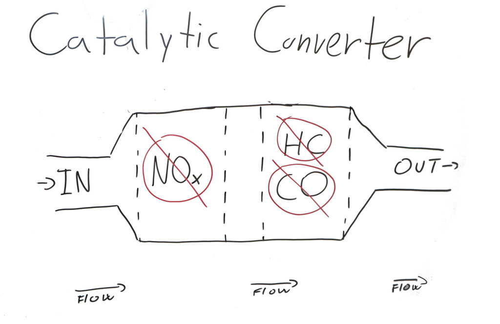
Rear O2 sensor determines efficiency of catalytic converter
High Voltage (around 0.7-1.0V): This indicates that there is a low amount of oxygen in the exhaust gases, meaning the air-fuel mixture is rich (more fuel than air). The catalytic converter has done its job and converted a significant amount of oxygen from the exhaust.
Low Voltage (around 0.1-0.3V): This indicates that there is a high amount of oxygen in the exhaust gases, meaning the air-fuel mixture is lean (more air than fuel). In this case, the downstream sensor is detecting that the catalytic converter hasn’t reduced much oxygen.
Oxygen sensor types
| Type | Number of Wires | Description |
|---|---|---|
| Narrowband | 1 wire | Signal only. |
| Narrowband | 2 wires | Signal and ground. |
| Narrowband | 3 wires | Signal, ground, and heater. |
| Narrowband | 4 wires | Signal, ground, and two heater wires. |
| Wideband | 5 wires | Signal, ground, reference, and heater wires. |
There are 2 main types of sensors used, either the classic narrowband sensor or more modern wideband (A/F) sensor.
Narrowband Oxygen Sensors:
- Measures: Rich or lean air-fuel mixture.
- Voltage Range: 0.1V to 0.9V (0.45V = ideal).
- Wires: 1 to 4 (signal, ground, and heater).
Wideband Oxygen Sensors:
- Measures: Precise air-fuel ratio (10:1 to 20:1).
- Voltage Range: Wider and more accurate.
- Wires: Typically 5 (signal, ground, reference, heater).
Locating oxygen sensors
In most cases, you will either have 2 oxygen sensors (inline engine) or 4 oxygen sensors (V-shaped engine). That is because a V-shaped engine will have 2 exhausts, 2 catalytic convertors, and therefore 4 oxygen sensors (2 for each convertor).
To locate which sensor is which, you can simply unplug the connector and hook up your OBD-II scanner. The fault code will tell you which connector you just unplugged. Bank 1 vs Bank 2 is explained here.
| O2S1B1 | Upstream oxygen sensor Bank 1 |
| O2S2B1 | Downstream oxygen sensor Bank 1 |
| O2S1B2 | Upstream oxygen sensor Bank 2 |
| O2S2B2 | Downstream oxygen sensor Bank 2 |
For some cars, there can be even 3 sensors for one exhaust system, up to 6 sensors in total if the engine is V-shape. In that case, you will have 2 upstream and 1 downstream sensor.
Testing Oxygen sensor with a multimeter
As a Member, you also have access to an electrical course, in case you are new to multimeter and electrical testing.
Wiring Guide for O2 Sensors
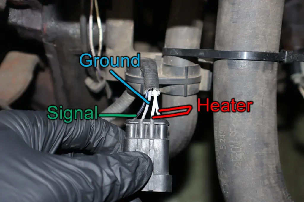
This picture shows how usually the wiring color scheme works.
Oxygen sensor wiring can vary, but here’s a general guide to wire colors and functions.
| Wire | Typical Color | Function |
|---|---|---|
| Signal wire | Black | Sends signal to ECU |
| Ground wire | Gray | Signal ground |
| Heater power | White | Power for the heater circuit |
| Heater ground | White | Ground for the heater circuit |
Here are 5 essential tests you can perform with a multimeter. Each test will include a table showing expected values and possible causes of abnormal readings.
1. Heater Circuit Resistance Test
Connect multimeter leads on 2 heater pins, and set multimeter reading to resistance.
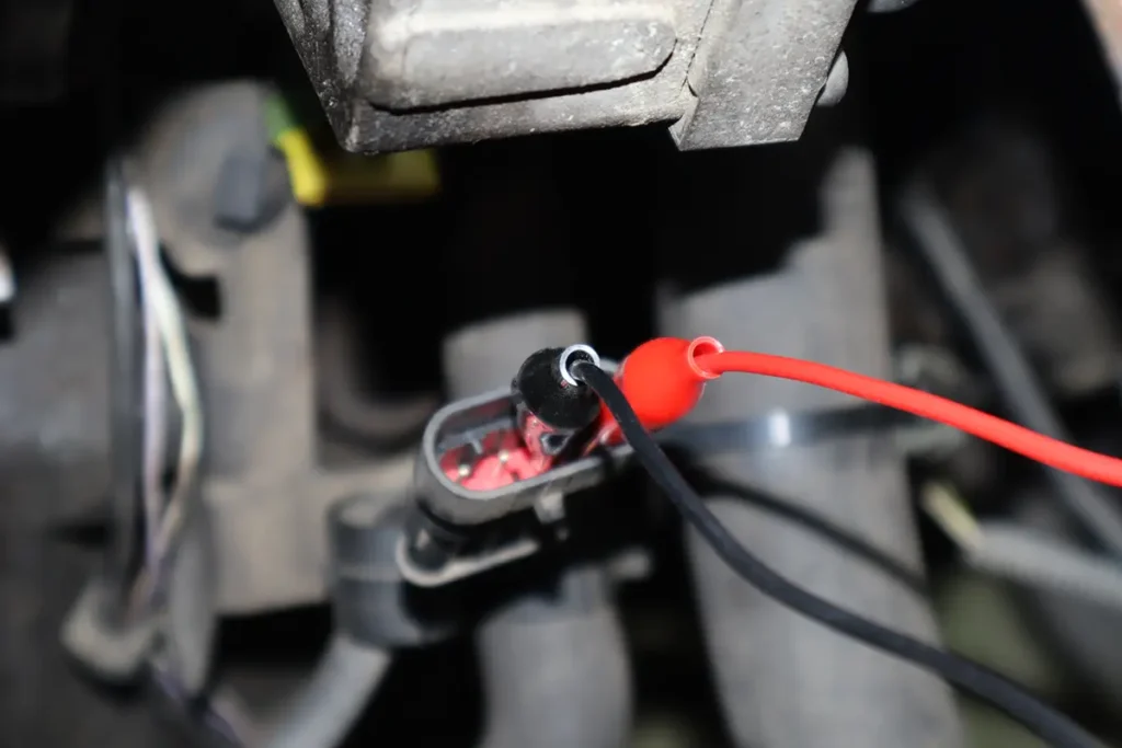
| Test | Measure resistance across heater wires on O2 sensor |
| Conditions | Connector disconnected, engine OFF |
| Expected value | 5-40 ohms |
| More than 40 ohms | Heater element may be faulty |
| Lower than 5 ohms, close to zero | Possible short in circuit |
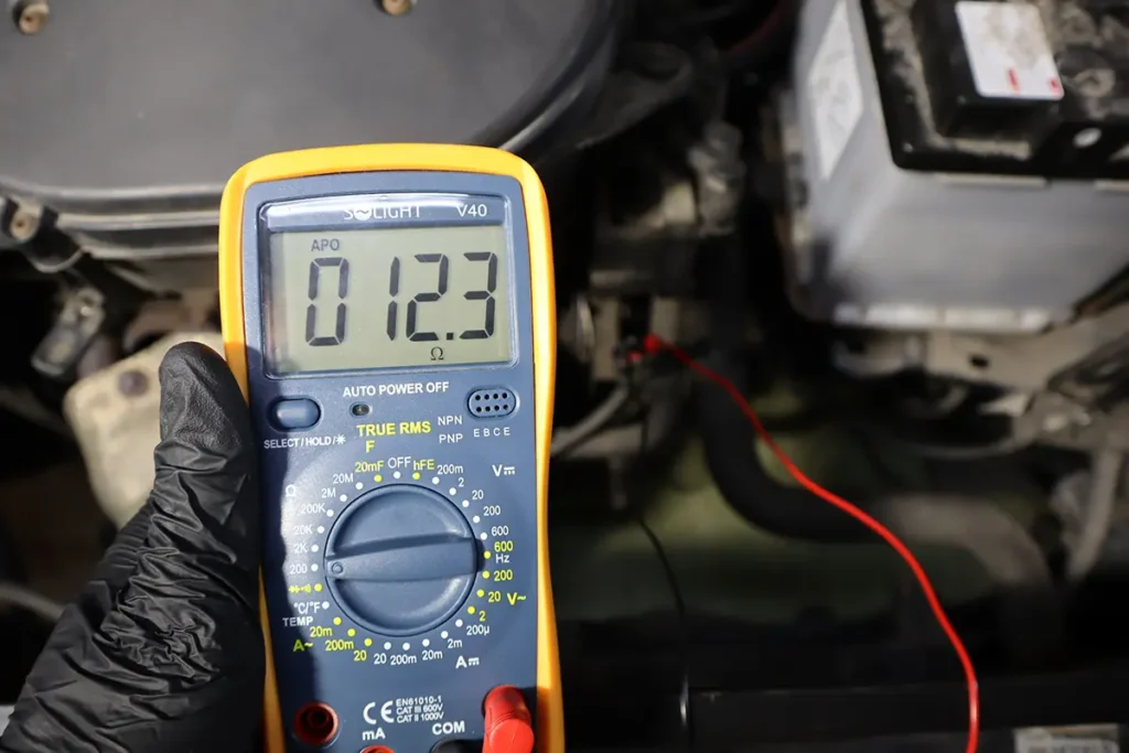
2. Signal Wire Voltage Test
Let’s simulate rich and lean conditions and check if the O2 sensor responds quickly. Back probe the signal wire with one lead, and connect the second lead on good ground.
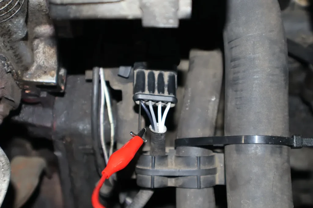
You can either simulate rich condition by spraying some brake cleaner in the intake or unplug some of the vacuum hose to let more air into the engine resulting in lean condition.
| Test | Measure voltage at the signal wire on O2 sensor |
| Conditions | Engine running, multimeter set to DC voltage |
| Expected value | 0.1V-0.9V for narrowband sensors 2.5V-3.3V for wideband sensors |
| Stuck at low voltage (~0.1V) | Lean condition or faulty sensor |
| Stuck at high voltage (~0.9V) | Rich condition or sensor issue |
3. Response Time Test
| Test | Snap throttle while engine is running and monitor voltage changes |
| Conditions | Engine running, quick throttle snap |
| Expected value | Voltage should quickly switch between 0.1V (lean) and 0.9V (rich) |
| Slow response | Sensor aging or contaminated |
| No response | Possible sensor failure or wiring issue |
In this test, we can see the sensor responds to rich conditions created by spraying brake cleaner into the intake, however, it should be oscillated before and not kept extremely low voltage under 0.1V before. Something is wrong with this test car.
4. Ground Continuity Test
Put one lead on the ground pin in the connector for the O2 sensor. The second lead goes to the engine block or negative battery terminal.
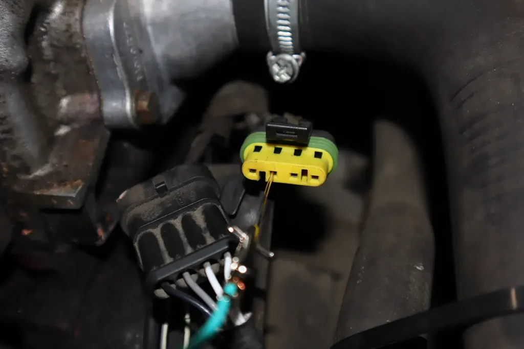
| Test | Measure continuity between ground wire and chassis ground |
| Conditions | Engine off, connector disconnected |
| Expected value | Low resistance (close to 0 ohms) |
| High resistance or no continuity | Poor ground connection or damaged wiring |
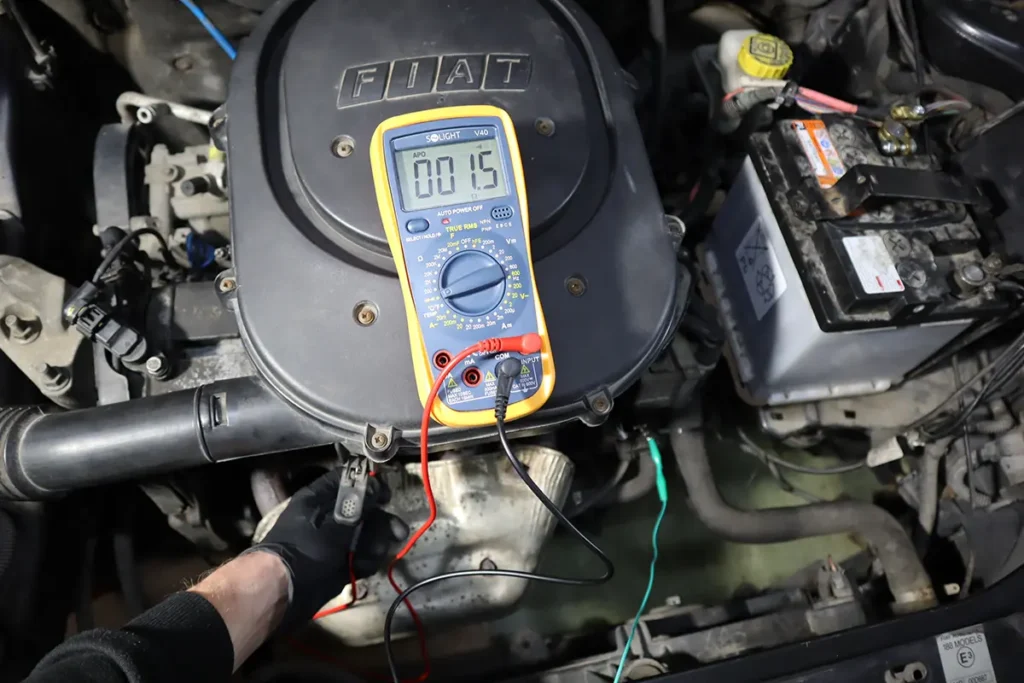
Although there is continuity which is good, the 1.5 Ohms of resistance seems a lot. For a good ground, you would want to see something closer to 0, like 0.2 Ohms.
Something is causing resistance in this vehicle.
5. Heater Power Test
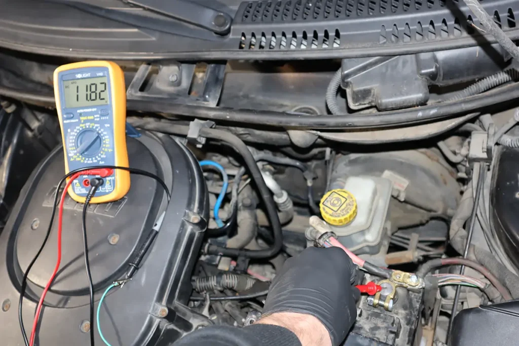
Put one multimeter lead on the power pin in the connector for the O2 sensor.
| Test | Measure voltage on the heater power wire on O2 sensor |
| Conditions | Ignition ON, engine off |
| Expected value | Battery voltage (~12V) |
| No voltage | Faulty wiring, fuse, or relay |
| Low voltage | Wiring resistance or ECU issue |
Test Oxygen sensor with OBD-II scanner
The best free app to test O2 sensors is Car Scanner ELM OBD2 which gives you very powerful ways of data displaying + logging. Open live data and select engine rpm, engine load, oxygen sensor 1 voltage, and oxygen sensor 2 voltage.
When a car is idling we can test only the front O2 sensor because ECU always makes sure it is heated with a heater element. Rear O2 is not heated all the time and to test it we will use driving tests.
Front O2 sensor
If the sensor is narrowband, it should oscillate from lean to rich condition constantly so switching from low (0.1V) to high (0-.9V) values.
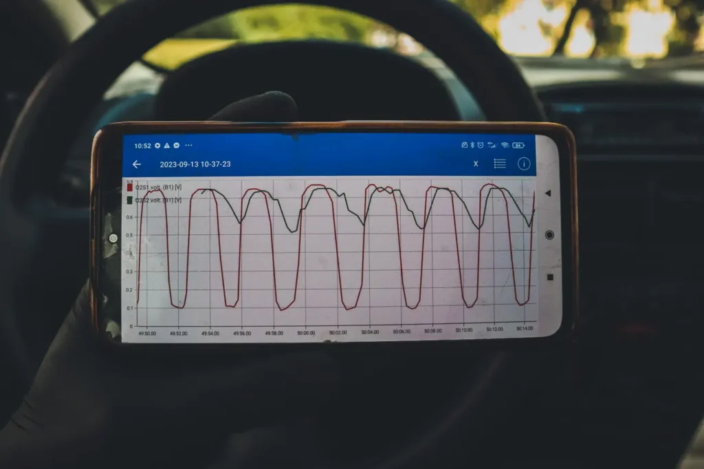
This is how the sensor should oscillate at idle. When you see a narrowband O2 sensor not oscillating at idle, there is a fault in the engine or in the sensor itself. You can test the sensor by stepping on the gas pedal for 2 seconds and then letting go. This will create a lean condition and the oxygen sensor should display lean voltage immediately after letting go of the gas pedal.
There can be also a faulty O2 sensor signal, which will show on your scanner. Check how the front sensor stopped reporting data to ECU even though engine is still running.
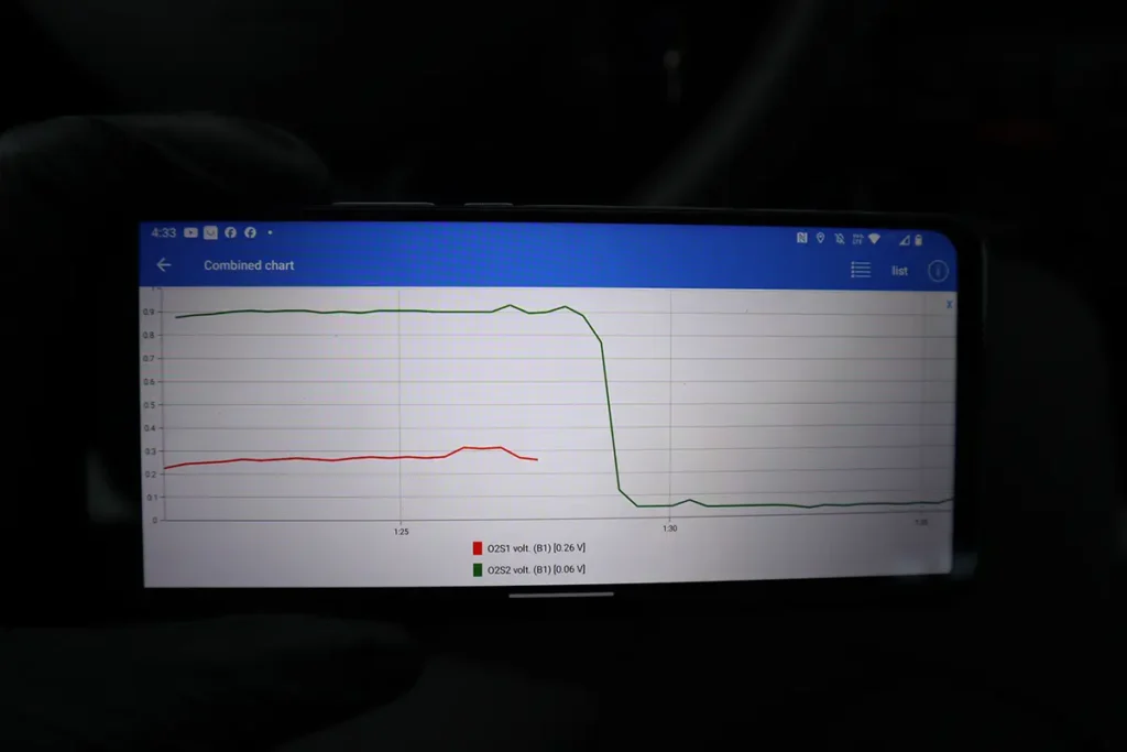
Important: A/F sensors (wideband) will usually display low voltage as rich condition and high voltage is for lean condition (opposite as narrowband sensor). To find out which voltage is for lean condition, simply press the gas pedal and let go. Once you let go off pedal the display voltage (either high or low) means a lean condition.
To find out how the sensor displays a lean and rich condition and also test the responsiveness of the A/F sensor we can do a simple gas pedal test.
- Press on the gas pedal for a few seconds with the engine at operating temperature
- Take your foot out of the pedal
- The voltage will jump to lean condition (in this case more voltage means more lean mixture)

Rear O2 sensor
Testing the rear sensor is important especially when you have the P0420 / P0430 fault codes for the low efficiency of the catalytic converter. These codes can be also caused by a failing downstream O2 sensor which is not evaluating data properly anymore.
Test 1: Acceleration/Deceleration
- Drive car in steady 1500-2000 RPM
- Full throttle for 2-3 seconds
- Take your foot off the gas pedal, and don’t use the brake for 2-3 seconds
We want to see the voltage keep at a steady 0.75V-0.9V during acceleration and then drop to 0.1V-0.3V and stay down for a few seconds after you take your foot off the gas pedal.

We want to see the rear oxygen sensor show a full range from 0.1V to 0.9V. During acceleration, it should stay up close to 0.9V and once we let go of the gas pedal the good downstream sensor will stay down close to 0.1V.
Test 2: Catalytic converter efficiency
For the next test, we will check both oxygen sensors and determine the health of the catalytic converter.
- Drive the car at a steady load of 40-50%
- Try to keep steady for at least 10 seconds
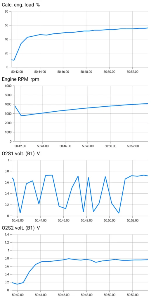
For this test, you want to see your upstream O2 sensor oscillating up and down, while the downstream O2 sensor must keep a steady high value (0.75-0.9V). We can see that the catalytic converter is working and is getting rid of harmful gases because it uses O2 in the process.
If we see the rear O2 sensor start oscillating and copy the front O2 sensor behavior, the catalytic converter cannot handle the amount of gases and it just lets them pass through.
If these test results are OK for you, you want to now increase the load of the gas pedal to 70% and check again. You want to see the same behavior of your data.

Hi, I am Juraj “Yuri” Lukacko. I got frustrated by unhelpful and scammy mechanics, so I decided to learn everything about car diagnostics myself. I test dozens of new car diagnostic tools every month along with learning new strategies to fix and customize cars. About Juraj Lukacko (Yuri)

