The P2537: Ignition Switch Accessory Position Circuit Low code indicates that there is a low voltage or signal issue in the ignition switch accessory position circuit. This can be caused by a faulty ignition switch, poor wiring, or loose or corroded connectors. A low voltage signal in the accessory position circuit can prevent certain electrical components, such as the radio or power outlets, from functioning properly.
P2537 – Quick Overview
| Code | Information |
|---|---|
| Meaning | P2537: Ignition Switch Accessory Position Circuit Low |
| Is it serious? | Moderately serious. This issue can lead to non-functional electrical accessories, potentially affecting user convenience. |
| Possible causes | – Low voltage or signal in the ignition switch accessory position circuit – Faulty ignition switch – Wiring or connector issues |
| How to diagnose? | – Measure the voltage in the ignition switch accessory position circuit – Inspect and test the ignition switch – Check wiring and connectors – Replace faulty components if needed |
Code Meaning
The P2537: Ignition Switch Accessory Position Circuit Low code means that there is insufficient voltage being detected in the accessory position of the ignition switch. This may result from an issue with the ignition switch itself, poor or damaged wiring, or loose connectors. The accessory position allows the driver to use various electronic features, such as the radio and auxiliary power, without starting the vehicle, and a low signal in this circuit can cause these features to stop working.
Step-by-step diagnostic guide
| Action | Description | Tools Needed |
|---|---|---|
| Check for Other Codes | Use an OBD-II scanner to determine if there are any additional related codes. Other codes could provide more information about issues related to the ignition system or accessory components. | OBD-II Scanner |
| Measure Voltage in the Accessory Position Circuit | Use a multimeter to measure the voltage in the ignition switch accessory position circuit. Compare the readings with the manufacturer’s specifications to determine if the voltage is below the expected range. | Multimeter |
| Inspect the Ignition Switch | Visually inspect the ignition switch for signs of wear, physical damage, or any issues affecting its operation in the accessory position. Make sure the key turns smoothly to the accessory position without resistance or play. | Flashlight, Safety Gloves |
| Check Wiring and Connectors | Inspect the wiring and connectors that are connected to the ignition switch. Look for loose, corroded, or broken connections. Damaged wiring can cause a drop in voltage, resulting in a low signal. Repair or replace any faulty wiring or connectors as needed. | Flashlight, Multimeter |
| Test the Ignition Switch | Use a multimeter to test the output voltage of the ignition switch in the accessory position. Verify that the switch provides the appropriate voltage to the accessory systems. If the voltage is low or inconsistent, replace the ignition switch. | Multimeter |
| Verify Power Supply and Ground Connections | Ensure that the ignition switch has an adequate power supply and a good ground connection when in the accessory position. A weak or unstable power supply or ground connection can result in low voltage in the accessory circuit. | Multimeter |
| Inspect Fuses and Relays | Check all fuses and relays that relate to the accessory circuit. Ensure that none of the fuses are blown and that relays are functioning correctly. Replace any faulty fuses or relays to restore proper operation. | Fuse Puller, Multimeter |
| Test Accessories in Accessory Position | Turn the ignition switch to the accessory position and test all connected accessories, such as the radio, power windows, and other accessory features. If any components do not respond, this could indicate further localized circuit issues. | Diagnostic Tool |
| Replace Faulty Components | Replace any faulty components identified during testing, such as the ignition switch, wiring, or connectors. Use OEM parts to ensure compatibility and proper function of the accessory circuit. | Replacement Parts, Vehicle Owner’s Manual |
| Clear the Code and Test the System | After completing the necessary repairs, use an OBD-II scanner to clear the P2537 code. Start the vehicle and test the ignition switch in the accessory position to ensure the system functions correctly and that voltage is within the proper range. | OBD-II Scanner, Vehicle Owner’s Manual |
| Recheck for Codes | Re-scan the vehicle to confirm that the P2537 code has not returned. If the code persists, further diagnostics may be necessary to identify any underlying issues. | OBD-II Scanner |
Free PDF: How to choose OBD2 scanner
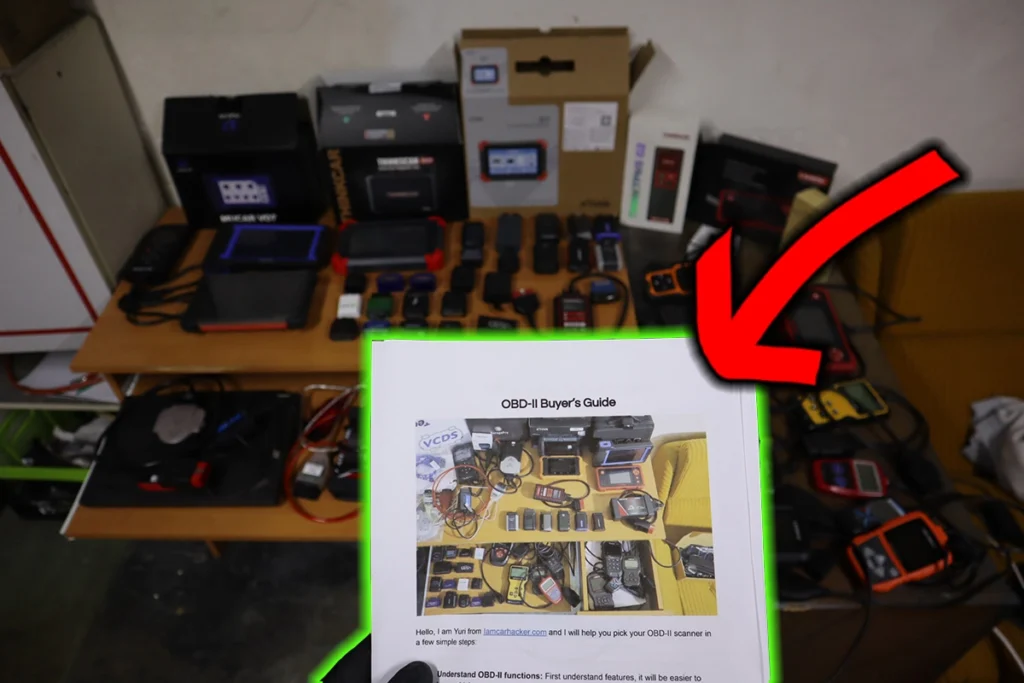
I’ve made you a free PDF to choose the OBD2 scanner in 5 minutes.
✅ Which OBD2 scanner is best?
✅ Which type should you get (DIY, Pro, Hobby)
✅ What is the best scanner for the exact brand/feature (e.g best for BMW)
✅ How to get a Bi-Directional tool for as cheap as $40
✅ Discount coupons for scanners
PDF is 100% free and it is designed to help you pick a scanner in less than a few minutes! Not a boring 50-page guide.
Just tell me where to send it.

Hi, I am Juraj “Yuri” Lukacko. I got frustrated by unhelpful and scammy mechanics, so I decided to learn everything about car diagnostics myself. I test dozens of new car diagnostic tools every month along with learning new strategies to fix and customize cars. About Juraj Lukacko (Yuri)