The P0BE3: Drive Motor Inverter Temperature Sensor “F” Circuit High refers to a fault where the temperature sensor “F” in the drive motor inverter circuit is reporting a higher than expected voltage. This issue could be caused by a malfunctioning sensor, wiring problems, or an electrical system issue. High voltage readings may affect the sensor’s ability to accurately monitor inverter temperature, potentially leading to performance issues or overheating.
P0BE3 – Quick Overview
| Code | Information |
|---|---|
| Meaning | P0BE3: Drive Motor Inverter Temperature Sensor “F” Circuit High |
| Is it serious? | Yes, incorrect temperature readings could cause the inverter to overheat, leading to potential damage or reduced performance. |
| Possible causes | – High voltage reading from sensor “F” – Faulty sensor or wiring issue – Electrical system problem |
| How to diagnose? | – Measure voltage from sensor “F” – Test sensor functionality – Inspect the electrical system for faults |
P0BE3 Meaning
The P0BE3 code indicates that the temperature sensor “F” in the drive motor inverter is producing a higher voltage than expected. This sensor is responsible for monitoring the inverter’s temperature, and high voltage readings may indicate a malfunction within the sensor, an issue with the wiring, or a problem in the electrical system. If the temperature is not properly monitored, the inverter may overheat, leading to performance issues or potential damage.
Step-by-step diagnostic guide
| Action | Description | Tools Needed |
|---|---|---|
| Check for Other Codes | Use an OBD-II scanner to identify any other related fault codes that might provide additional information. | OBD-II Scanner |
| Measure Voltage from Sensor “F” | Use a multimeter to measure the voltage output from sensor “F” and compare it to the vehicle manufacturer’s specifications. Ensure the voltage is within the correct range. | Multimeter, Diagnostic Tool |
| Test Sensor Functionality | Check if sensor “F” is functioning correctly by using a diagnostic tool to verify it is providing accurate data to the control module. | Multimeter, Diagnostic Tool |
| Inspect the Electrical System | Ensure that the vehicle’s electrical system is functioning properly and supplying the correct voltage to sensor “F”. Look for electrical issues such as high voltage supply. | Multimeter, Flashlight, Safety Gloves |
| Inspect Wiring and Connections | Examine the wiring and connectors for damage, loose connections, or corrosion that could be causing the high voltage readings. | Flashlight, Multimeter, Wiring Diagram |
| Clear the Code and Test Drive | After completing repairs, clear the fault code using an OBD-II scanner and perform a test drive to verify that the issue is resolved. | OBD-II Scanner, Vehicle Owner’s Manual |
| Recheck for Codes | After the test drive, re-scan the vehicle to ensure that the P0BE3 code does not return. | OBD-II Scanner |
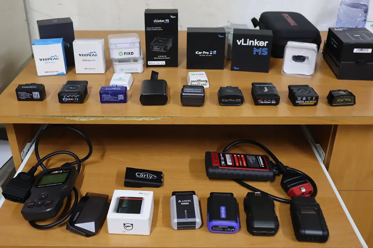
OBD-II scanner Buyer’s Guide
- Scanner features explained
- Different types of scanners
- Scanners for coding/odometer/ECU/checks
- Best picks + discount codes

Hi, I am Juraj “Yuri” Lukacko. I got frustrated by unhelpful and scammy mechanics, so I decided to learn everything about car diagnostics myself. I test dozens of new car diagnostic tools every month along with learning new strategies to fix and customize cars. About Juraj Lukacko (Yuri)