The P2545: Torque Management Request Input Signal ‘A’ Range/Performance code indicates an issue with the range or performance of the torque management request input signal ‘A’. This could be due to a faulty control module, or issues with the wiring or connectors that affect the signal’s accuracy. Proper torque management is critical for smooth power delivery during gear shifts and other operations to prevent damage to the drivetrain.
P2545 – Quick Overview
| Code | Information |
|---|---|
| Meaning | P2545: Torque Management Request Input Signal ‘A’ Range/Performance |
| Is it serious? | Moderately serious. Faulty torque management can cause issues like harsh shifting, loss of power, or damage to drivetrain components due to improper torque regulation. |
| Possible causes | – Range or performance issues with the torque management request input signal ‘A’ – Faulty torque management control module – Wiring or connector problems |
| How to diagnose? | – Test the range and performance of the torque management request input signal ‘A’ – Inspect and test the torque management control module – Check wiring and connectors – Replace faulty components if needed |
Code Meaning
The P2545: Torque Management Request Input Signal ‘A’ Range/Performance code indicates that the signal from input ‘A’ of the torque management system is outside its expected range or is not performing correctly. This issue may be due to a malfunction in the control module, wiring faults, or problems with connectors. Torque management is essential for controlling engine power during certain conditions, such as gear changes, to ensure smooth operation and to protect the drivetrain from damage.
Step-by-step diagnostic guide
| Action | Description | Tools Needed |
|---|---|---|
| Check for Other Codes | Use an OBD-II scanner to determine if there are additional related codes present. These codes may provide more information about other components affected or related to the torque management system. | OBD-II Scanner |
| Test the Range and Performance of Input Signal ‘A’ | Use a diagnostic scanner to monitor the live data of torque management request input signal ‘A’. Compare the values to the manufacturer’s specifications to determine if they are within the expected range. Any deviations may indicate a malfunction. | Diagnostic Tool, Multimeter |
| Inspect the Torque Management Control Module | Visually inspect the torque management control module for any signs of damage, including corrosion, burnt components, or loose connections. Ensure the module is properly mounted and free from physical defects that could affect its operation. | Flashlight, Safety Gloves |
| Perform a Wiggle Test on Wiring and Connectors | While monitoring the signal with a scan tool, gently move or “wiggle” the wiring harness and connectors. If the signal fluctuates during this test, a faulty connection or damaged wiring may be the cause. | Diagnostic Scanner, Multimeter |
| Check Wiring and Connectors for Integrity | Inspect the wiring and connectors related to input signal ‘A’. Look for frayed wires, loose connectors, or corroded terminals that could cause improper or fluctuating signals. Replace or repair any components that appear damaged. | Flashlight, Multimeter |
| Measure Voltage and Signal Stability | Use a multimeter to measure the voltage at the control module and compare it with the specifications. If the voltage or signal fluctuates or falls outside the expected range, there could be a wiring or sensor fault. Ensure that the power supply and ground are stable. | Multimeter |
| Verify Power Supply and Ground for the Control Module | Ensure that the torque management control module is receiving a proper and stable power supply and that the ground connection is secure. Issues with power or ground can impact the module’s ability to manage torque requests properly. | Multimeter |
| Inspect Fuses and Relays | Check all fuses and relays associated with the torque management system. Ensure that no fuses are blown and that the related relays are functioning correctly. Replace any defective fuses or relays. | Fuse Puller, Multimeter |
| Replace Faulty Components | If any component is found to be faulty during the diagnostics, such as the control module, connectors, or wiring, replace them with OEM parts to ensure compatibility and proper functionality of the torque management system. | Replacement Parts, Vehicle Owner’s Manual |
| Clear the Code and Test the System | After completing the repairs, clear the P2545 code using an OBD-II scanner. Start the vehicle and monitor the torque management request input signal to ensure the signal falls within the expected range and no new codes are generated. | OBD-II Scanner, Vehicle Owner’s Manual |
| Recheck for Codes | Re-scan the vehicle to verify that the P2545 code has not returned. If the code persists, further diagnostics may be required to identify other underlying issues with the torque management system. | OBD-II Scanner |

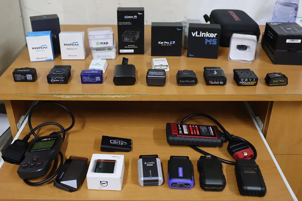
OBD-II scanner Buyer’s Guide
- Scanner features explained
- Different types of scanners
- Scanners for coding/odometer/ECU/checks
- Best picks + discount codes
I test OBD-II scanners and make DIY Engine diagnostics guides to help you solve your car problems without having to depend on the mechanic. A lot of them will try to scam you or are just no help at all. About Juraj Lukacko